Techno Treacle
Architecture, IT, CAD, for a well know Architecture Practice making top buildings. We use Microstation, Revit, all the usual Adobe Products, PCs (not Macs although we would quite like to change back), 2.5 offices, and a great working environment.
Thursday, 14 July 2011
Wednesday, 22 June 2011
Converting Linestyles from DGN files Microstation to DWG
Active linestylescale (LTSCALE in AutoCAD terms) should be set to 1
Set Line Code Scale to 0.0 in DWG Options. This is the confusing one, if this is set to 0.0, the linestyle used for the DWG drawing will be as it looks in Microstation. Therefore make sure you fit the view first before exporting.
Export to DWG
Linestyles will be set to the length based on the view in MicroStation.
Alternatively, remap linestyles to AutoCAD styles
Set LTSCALE to the scale of the drawing
How to not lose clipped patterns when saving to DWG
There has been a but in Microstation for a while which loses the patterns of shapes that fall accross the clip line of a DGN when saved to DWG. With v8i this is no longer a problem as long as you follow these simple guidelines:
1. Make sure the patterns are associative
2. Make sure the DWG settings are set to Merge to Cell (and not just Merge)
When save as or export is used, the shapes should be recreated as a new shape of shape with the hatch pattern intact.
Tuesday, 26 October 2010
How to use Vector works dwg files in a Revit model
You may not have problems with these files but if you do it is likely to be caused by shared cells (Microstation term) or cells (also Microstation term) and also if the model is a long way from the origin this also causes problems. The problems occur with the file appearing to be over the 20 mile limit. This because the cells or shared cells have an origin that is more than 20 miles from the elements. Do the following
1. Open the dwg in Microstation
2. Save the file as a dgn
3. Move the global origin to close the the drawing or in the middle of the drawing (go= )
4. Check that the global origin has moved by placing a line from xy=0
5. Save settings to save the position of the global origin
6. Select all the shared cells by using the Select By Attributes tool
7. Drop the shared cells to geometry only. Make sure this has happened
8. Save the file back as a DWG and then reload into your Revit model
Revit printing to A3 Black and White printer Canon 5055N
Wednesday, 20 October 2010
Microstation Luxology Engine failure

When we moved to service release 2 of Microstation V8i Luxology had a problem. Half way through rendering anything (of any size) the process would stop with the message the the luxology engine had failed. If we tried the same rendering with a completely default install with no network workspace there was no problem. Also some users did not experience the problem. These were users that had already used Luxology with other earlier versions of v8i. The problem was that the luxology history variable had not been set. This can be set manually from the luxology settings (at the bottom). If it is set manually there is no problem. The other way to set it, is to use the MS_LUXOLOGY_HISTORY variable in your standard config. We have set ours to $(400-fcbdata) which is mapped to the project data folder. This variable sets where a thumbnail of the previous render is stored.
Tuesday, 19 October 2010
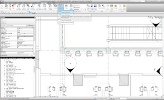
Aquiring Coodinates in Revit - Its easy when you know how

Revit has a strange way of using a coordinate system. Traditional CAD (AutoCAD and Microstation) allows the use of Auxillary coordinate systems so you can have a number of different oring points, North angles and relative positions.
Revit is different. With Revit, models should always be drawn at the centre of the file near the world 0,0 point. This can be found by viewing the default "Site" view in a Revit file. The site view has the survey 0,0 and the world 0,0 turned on so they can be viewed.
To add a true coodinate system on to the Revit model, first link a DWG (or Revit file) that contains a survey point or grid. if you are starting to work with a project that already has a grid in the correct place, use the grid file as this contains the key monument points for the whole project.
When you link the DWG survey file or grid file, position it center to center so that the grid appears near the survey and world 0,0 points. It is likey that the grid file will appear at an agle too.
Now the important bit. Make sure that you only move the linked CAD file and not the model file itself. With other CAD systems you usually work the other way round and you never move the attached grid file.
Rotate the linked file to the correct angle so that the grid runs left to right and up to down correctly. Now position the grid in exactly the right position by moving the linked file. Once the linked file is in the correct position and the correct angle you are now ready to aquire the coordinates.
click on Manage (from within the Revit menus) then Coordinates then Aquire Coordinates. Now click on the linked CAD file. This will add the coordinate system to the Revit file and you will now be able to link other revit files and CAD files using shared coordinates (instead of center to center etc) so that the files appear in exactly the same location.
Subscribe to:
Comments (Atom)
