Architecture, IT, CAD, for a well know Architecture Practice making top buildings. We use Microstation, Revit, all the usual Adobe Products, PCs (not Macs although we would quite like to change back), 2.5 offices, and a great working environment.
Tuesday, 26 October 2010
How to use Vector works dwg files in a Revit model
Revit printing to A3 Black and White printer Canon 5055N
Wednesday, 20 October 2010
Microstation Luxology Engine failure

When we moved to service release 2 of Microstation V8i Luxology had a problem. Half way through rendering anything (of any size) the process would stop with the message the the luxology engine had failed. If we tried the same rendering with a completely default install with no network workspace there was no problem. Also some users did not experience the problem. These were users that had already used Luxology with other earlier versions of v8i. The problem was that the luxology history variable had not been set. This can be set manually from the luxology settings (at the bottom). If it is set manually there is no problem. The other way to set it, is to use the MS_LUXOLOGY_HISTORY variable in your standard config. We have set ours to $(400-fcbdata) which is mapped to the project data folder. This variable sets where a thumbnail of the previous render is stored.
Tuesday, 19 October 2010
Aquiring Coodinates in Revit - Its easy when you know how

Revit has a strange way of using a coordinate system. Traditional CAD (AutoCAD and Microstation) allows the use of Auxillary coordinate systems so you can have a number of different oring points, North angles and relative positions.
Revit is different. With Revit, models should always be drawn at the centre of the file near the world 0,0 point. This can be found by viewing the default "Site" view in a Revit file. The site view has the survey 0,0 and the world 0,0 turned on so they can be viewed.
To add a true coodinate system on to the Revit model, first link a DWG (or Revit file) that contains a survey point or grid. if you are starting to work with a project that already has a grid in the correct place, use the grid file as this contains the key monument points for the whole project.
When you link the DWG survey file or grid file, position it center to center so that the grid appears near the survey and world 0,0 points. It is likey that the grid file will appear at an agle too.
Now the important bit. Make sure that you only move the linked CAD file and not the model file itself. With other CAD systems you usually work the other way round and you never move the attached grid file.
Rotate the linked file to the correct angle so that the grid runs left to right and up to down correctly. Now position the grid in exactly the right position by moving the linked file. Once the linked file is in the correct position and the correct angle you are now ready to aquire the coordinates.
click on Manage (from within the Revit menus) then Coordinates then Aquire Coordinates. Now click on the linked CAD file. This will add the coordinate system to the Revit file and you will now be able to link other revit files and CAD files using shared coordinates (instead of center to center etc) so that the files appear in exactly the same location.
Monday, 26 July 2010
Microstation Bentley Architecture - Space Labels to more than 0 decimal places
TFANNOTATE_AREAPRECISION
Decimal point accuracy for Actual Area and Program area settings values can be controlled by a user defined configuration variable, TFANNOTATE_AREAPRECISION. The number of trailing decimal numbers can be set from 0 to 6, with 2 being the default.
Thursday, 10 June 2010
Tuesday, 8 June 2010
Revit - Editing Grid Head Size to work nicely at all scales
Monday, 7 June 2010
Railings in Revit


Drawing a Panel from scratch using the panel template. If one creates an extrusion in the left or right hand view clicking to the four corners of the reference planes like this creates a panel 600mm wide.
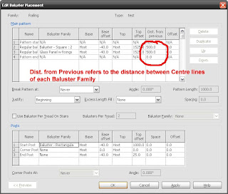
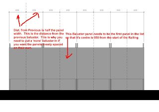
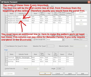
Now at last here is the top tip for using the ballusters. Make sure you have half the panel width in the Dist. from previous if you do not want a gap between each panel or balluster. This is because the setout position is the centre of the panel. Therefore the Distance from Previous is actually the distance of the start of the next panel from the centre (setout line) of the previous panel.
Here are some useful descriptions of the railing settings:
At the bottom under the setction titled POSTS the Start Post has a setting called SPACE. This setting is the amount that the start post (or panel is offset to the right of the start of the ballustrade. The amount in from the end of the ballustrade.
Friday, 4 June 2010
Revit Stairs Interesting fact about risers
If you want to change the maximum riser height later, you will need to duplicate the stair type. If you try to change the maximum riser height of the existing stair, nothing will happen. Beware.
Thursday, 3 June 2010
Wednesday, 2 June 2010
Adding the 3GB switch to the startup .ini to give Revit the chance of more RAM
In lay terms, Windows usually allocates 2 gigs of RAM to programs and 2 gigs to the system. With the switch it changes it to 3GB for programs and 1GB for other things.
This is how you do it.
a) Access the boot.ini file by opening the System Properties dialog on "My Computer". Under the Advanced tab and Startup and Recovery press Settings. In the startup and recovery dialog press the edit button. This should open a text file with something close to the following content:
[boot loader]
timeout=30
default=multi(0)disk(0)rdisk(0)partition(1)\WINDOWS
[operating systems]
multi(0)disk(0)rdisk(0)partition(1)\WINDOWS="Microsoft Windows XP Home Edition" /fastdetect /noexecute=optin
b) Were are going to modify it and make a failsafe so that if the mod doesn't work we can go back to the original setting:
Copy the last line and add /3GB to the end of it (make sure you spell it right). Between the parentheses type 3GB at the end so you'll be able to recognize it when XP restarts. Also if you don't have noexecute=optin add that too. The whole thing will look like this
[boot loader]
timeout=30
default=multi(0)disk(0)rdisk(0)partition(1)\WINDOWS
[operating systems]
multi(0)disk(0)rdisk(0)partition(1)\WINDOWS="Microsoft Windows XP Home Edition" /fastdetect /noexecute=optin multi(0)disk(0)rdisk(0)partition(1)\WINDOWS="Microsoft Windows XP Home Edition 3GB" /fastdetect /noexecute=optin /3GB
Friday, 28 May 2010
Revit Renders Unable to Save Image to Project or Export

You set your machine to render (at least above the draft setting) and it renders without problems but when it has finished rendering you are unable to Save the Image to the Project or Export. It seems to be something to do with a memory leak. The only current workaround is to make sure you reboot the machine and open Revit and render straight away (without doing any work or opening other files). Also make sure that you have as little running as possible and as much memory freed up. Also make sure you have the 3GB switch on allowing Windows to use more than 2GB for one application.
Showing Masses in 3D View Window in Revit


To create a context model in Revit you can import DWG (or Sketchup 5 if you are lucky) into Revit. If you import it straight in, the geometry does not work well as a massing model to render. The trick is to create a new Mass and import the DWG into the Mass. This works well. However, by default the Masses will not show in a 3d View if referenced into another Revit File. There is an obscure tickbox called Imports in Families within the visibility Graphics for the view. This needs to be ticked in addition to the Show Mass button as well as the Mass section of the visibilty Graphics.
I have found the tick box in VG and Imports in Families. I realised that because you have to import geometry into a Mass to create a decent context model this is considered to be an Import in Families. Therefore this must be ticked for the view. The template for view creation does not have this on by default whereas the 3D view does. So we are happy again.


