Revit has a strange way of using a coordinate system. Traditional CAD (AutoCAD and Microstation) allows the use of Auxillary coordinate systems so you can have a number of different oring points, North angles and relative positions.
Revit is different. With Revit, models should always be drawn at the centre of the file near the world 0,0 point. This can be found by viewing the default "Site" view in a Revit file. The site view has the survey 0,0 and the world 0,0 turned on so they can be viewed.
To add a true coodinate system on to the Revit model, first link a DWG (or Revit file) that contains a survey point or grid. if you are starting to work with a project that already has a grid in the correct place, use the grid file as this contains the key monument points for the whole project.
When you link the DWG survey file or grid file, position it center to center so that the grid appears near the survey and world 0,0 points. It is likey that the grid file will appear at an agle too.
Now the important bit. Make sure that you only move the linked CAD file and not the model file itself. With other CAD systems you usually work the other way round and you never move the attached grid file.
Rotate the linked file to the correct angle so that the grid runs left to right and up to down correctly. Now position the grid in exactly the right position by moving the linked file. Once the linked file is in the correct position and the correct angle you are now ready to aquire the coordinates.
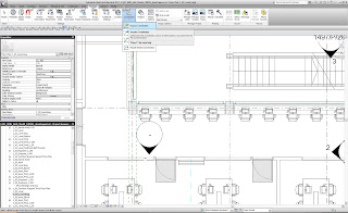
click on Manage (from within the Revit menus) then Coordinates then Aquire Coordinates. Now click on the linked CAD file. This will add the coordinate system to the Revit file and you will now be able to link other revit files and CAD files using shared coordinates (instead of center to center etc) so that the files appear in exactly the same location.
No comments:
Post a Comment